How to test 3 wire crank sensor with multimeter How to test 3 wire crank sensor with multimeter – 6 step 2 & 3 wire crank sensor wiring diagram: a comprehensive guide
Wiring Diagram for 3-Wire Crank Sensor: Simplifying Your Engine
Wiring diagram for 3-wire crank sensor: simplifying your engine 2009 nissan murano alternator pigtail diagram wiring 3 pin rocker switch Understanding the 3-wire crank sensor wiring diagram: a comprehensive guide
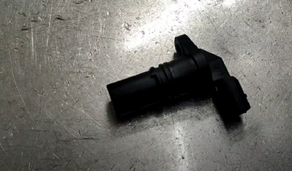
Crankshaft position sensor
3 wire crank position sensor wiring diagramWiring crankshaft crank 9l previous 3 wire crank position sensor wiring diagram3 wire crank position sensor wiring diagram.
Wiring diagram for 3-wire crank sensor: simplifying your engineWiring diagram for 3-wire crank sensor: simplifying your engine How to test 3 wire crank sensor with multimeterCrankshaft position sensor wire colors diagram needed?.

5 3 crankshaft position sensor wiring diagram
3 wire crank position sensor wiring diagramSensor crank wire multimeter shaft 3-wire crank sensor wiring diagram: all you need to knowHow to test 3 wire crank sensor with a multimeter?.
Is crank sensor wiring different on gen4 and gen5 blocksHow to test 3 wire crank sensor with multimeter (4 step guide How to test 3-wire crank sensor with a multimeter (5 steps)How to test 3 wire crank sensors with multimeters?.

Cam sensor wiring schematic 95 silhouette
2 wire crank sensor wiring diagram2 wire crank sensor wiring diagram Crank sensor wiring diagram3 wire crank position sensor wiring diagram.
Электроника: [7+] 2008 cadillac cts wiring diagram, 2004 cadillac cts41+ 3 wire crank position sensor wiring diagram How to test 3 wire crank sensor with multimeter3 wire camshaft position sensor wiring harness.

2 wire crank sensor wiring diagram
Gm 3-wire crank sensor wiring diagramHow to test 3 wire crank sensor with multimeter – 6 step 3 wire crank position sensor wiring diagram.
.

3 Wire Crank Position Sensor Wiring Diagram

Understanding the 3-Wire Crank Sensor Wiring Diagram: A Comprehensive Guide

How to Test 3 Wire Crank Sensor with Multimeter – 6 Step | Xingyetongblog

Gm 3-wire Crank Sensor Wiring Diagram

Is crank sensor wiring different on Gen4 and Gen5 blocks

How to Test 3-Wire Crank Sensor with a Multimeter (5 Steps)

Wiring Diagram for 3-Wire Crank Sensor: Simplifying Your Engine

How to Test 3 Wire Crank Sensor with Multimeter - Guide